Subaru Time Attack / 2025 / Applied Design & Engineering
Regulation-Driven DRS Wing Development Using Scan-Based Vehicle Integration
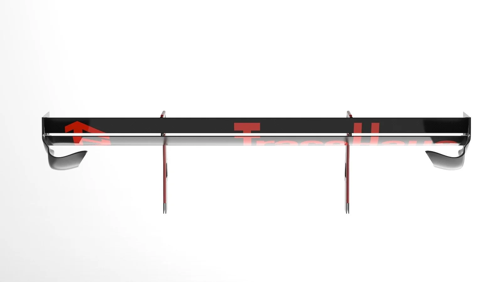
Design and engineering of a motorsport-inspired rear wing with an integrated Drag Reduction System (DRS). The system was developed using 3D scan data to define mounting datums, aerodynamic packaging, and structural load paths while meeting motorsport dimensional constraints and manufacturability requirements.
The Challenge
Design a functional rear wing with an integrated Drag Reduction System (DRS) that could be accurately integrated onto an existing track-prepared vehicle while operating within motorsport dimensional constraints.
The project required translating real vehicle geometry into a manufacturable aerodynamic assembly while addressing several technical challenges:
Establishing precise mounting geometry using scan-derived vehicle datums
Maintaining structural stiffness and load transfer through tall wing supports
Defining aerodynamic surfaces and DRS articulation within regulated dimensional limits
Ensuring clearance with bodywork, trunk operation, and rear visibility zones
Developing a fabrication strategy compatible with realistic manufacturing processes

Constraints & Requirements
Regulatory
Maximum wing span and chord envelope
Endplate dimensional limits
Mounting height restriction
Controlled DRS articulation range
Vehicle Packaging
Complex trunk curvature
Alignment to chassis hard points
Clearance to rear glass and bodywork
Diffuser and wake interaction
Structural
Load transfer through tall supports
Bending and buckling resistance
Mount reinforcement strategy
Serviceable fastener layout
Manufacturing
Material selection for stiffness vs weight
Sheet/composite fabrication feasibility
Bend and assembly constraints
Modular component replacement
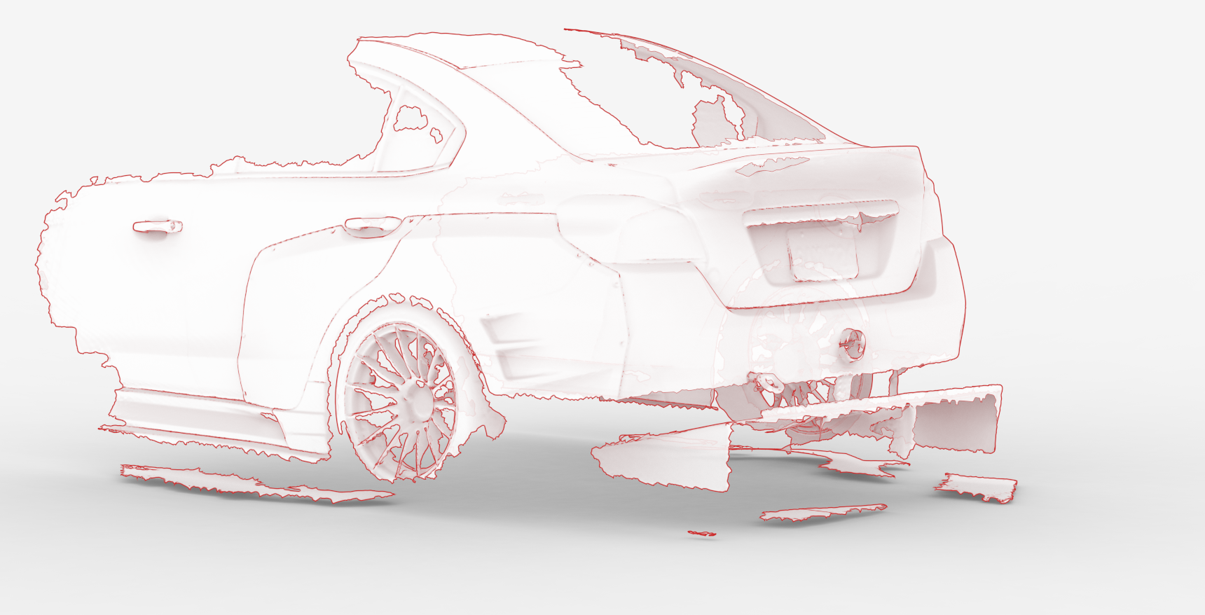
Geometry Acquisition & Reference Definition
Accurate rear geometry was captured via 3D scanning to establish mounting datums and regulatory envelopes prior to aerodynamic development.
Reference Objectives
Capture rear deck geometry
Define structural mounting datums
Establish aerodynamic placement envelope
Validate DRS articulation clearance
Data Processing
Mesh cleanup and alignment
Surface deviation verification
Reference plane and centerline extraction
Conversion into CAD reference geometry
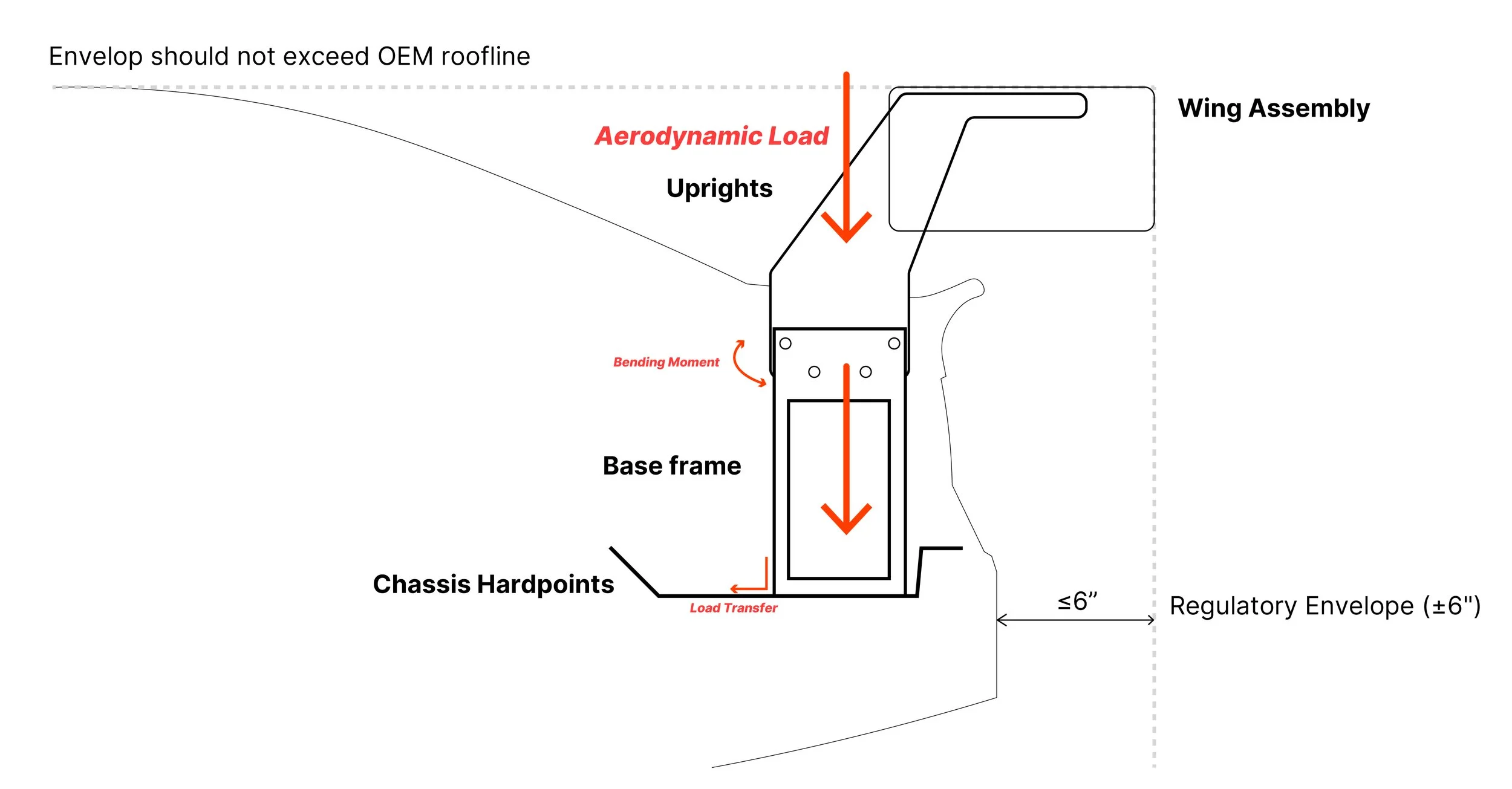
Structural Integration Strategy
Aerodynamic load at the wing plane generates vertical force and base bending moment at the upright interface. The mounting geometry transfers amplified loads into reinforced chassis hardpoints while remaining within regulatory envelope constraints.
Vertical aerodynamic load at wing assembly
Upright height amplifies base bending moment
Base frame distributes load into chassis hardpoints
Integration constrained within ±6" regulatory envelope
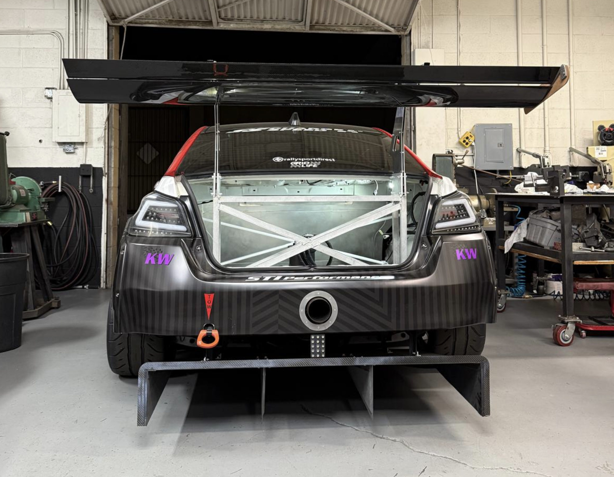
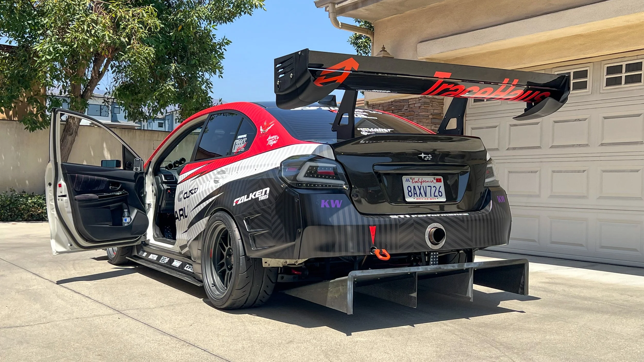
Final Integrated System
The custom DRS wing system was developed, prototyped, and integrated onto a track-prepared vehicle within class dimensional constraints. The final assembly combines aerodynamic geometry, structural mounting strategy, and fabrication-ready components.

Development & Validation
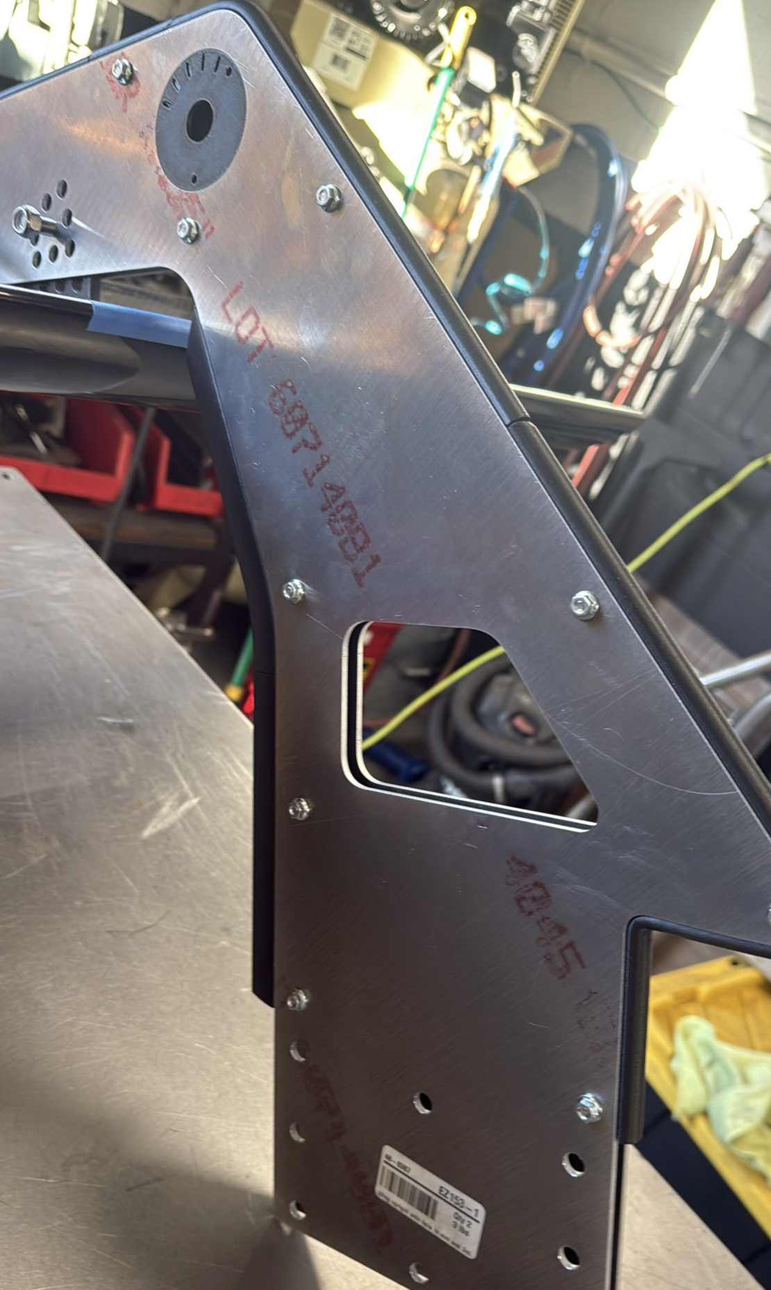
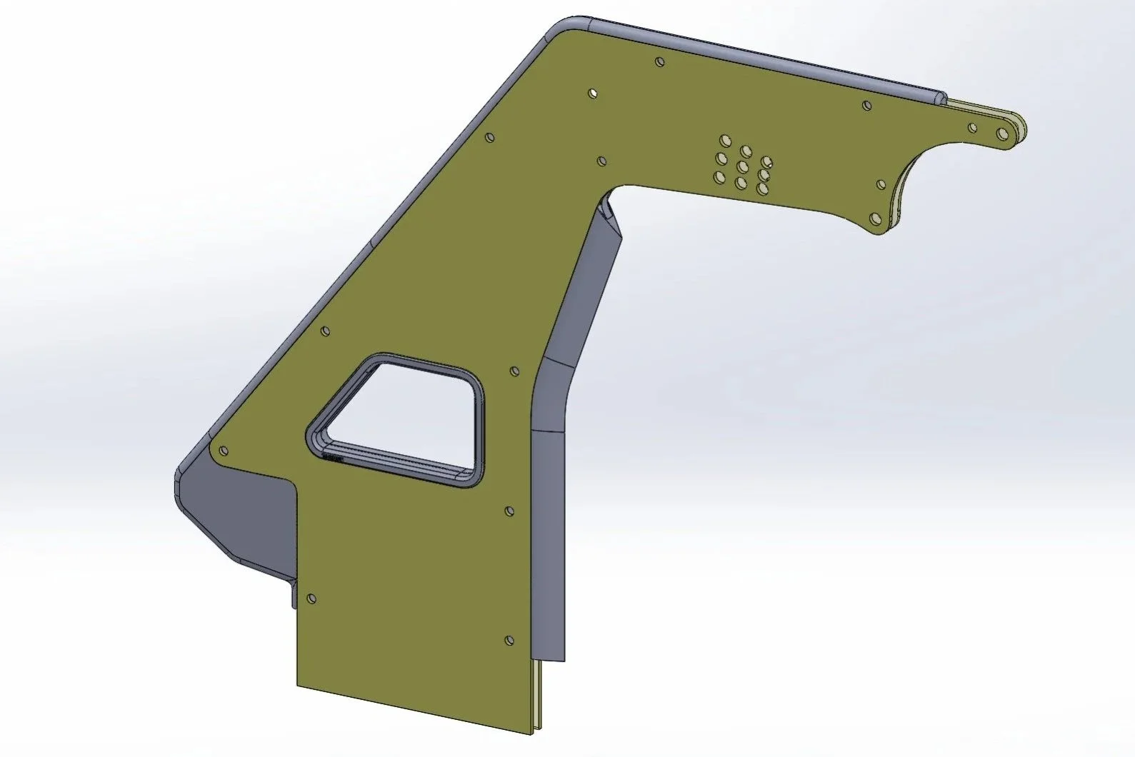
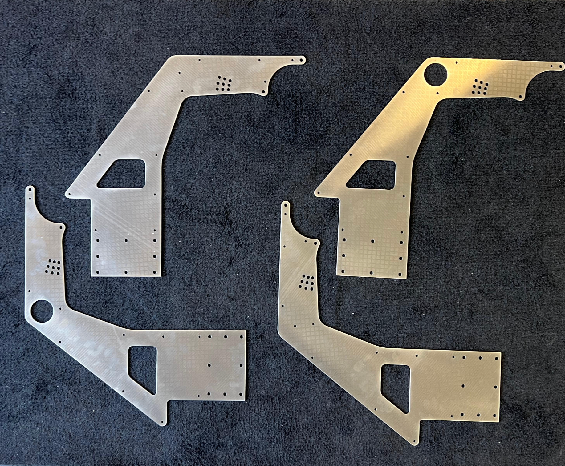
Structural Uprights
Scan-derived CAD geometry translated into CNC-cut 7075 aluminum uprights.
Hole patterns and section geometry iterated to optimize stiffness-to-weight ratio and load transfer efficiency within manufacturing constraints.
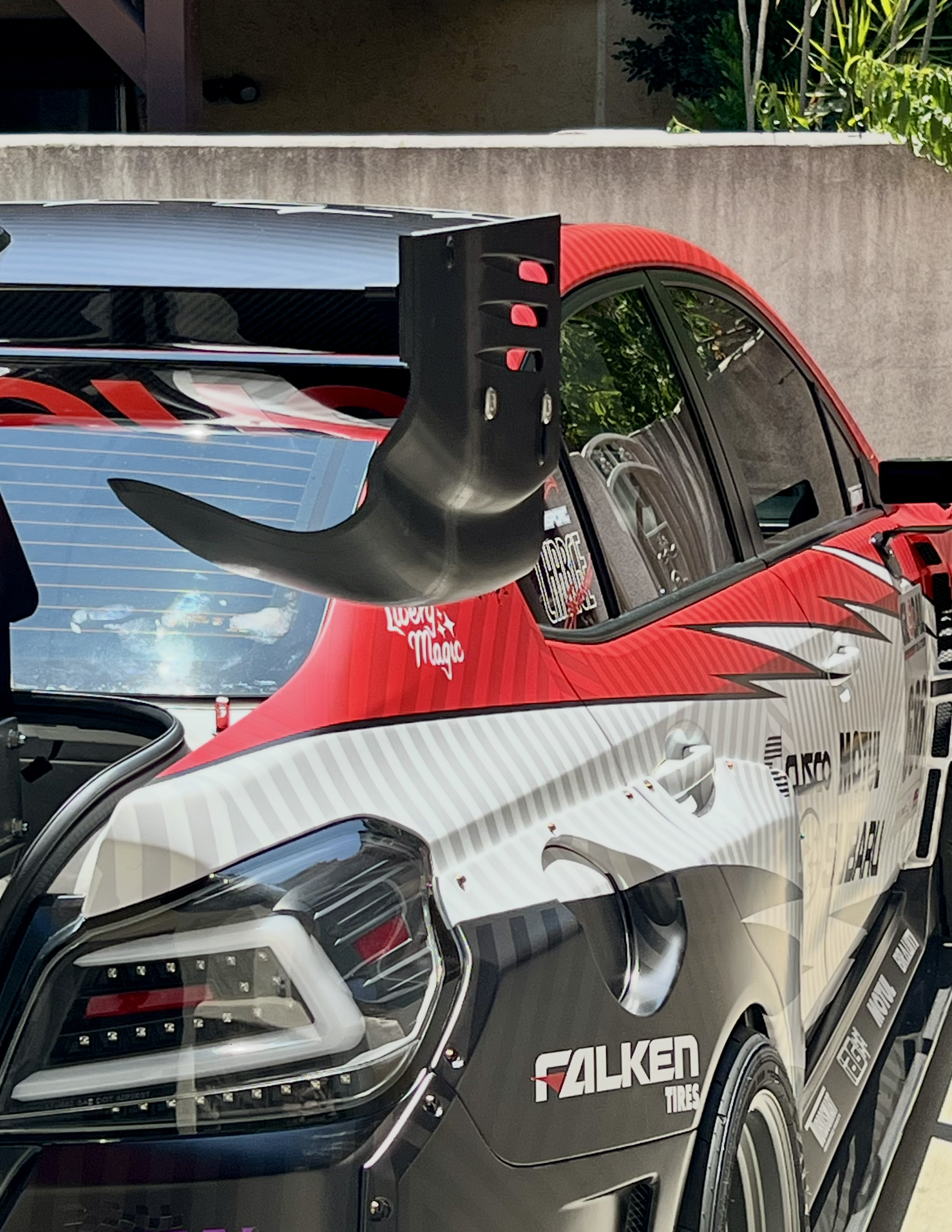
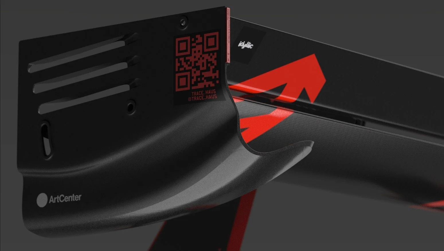
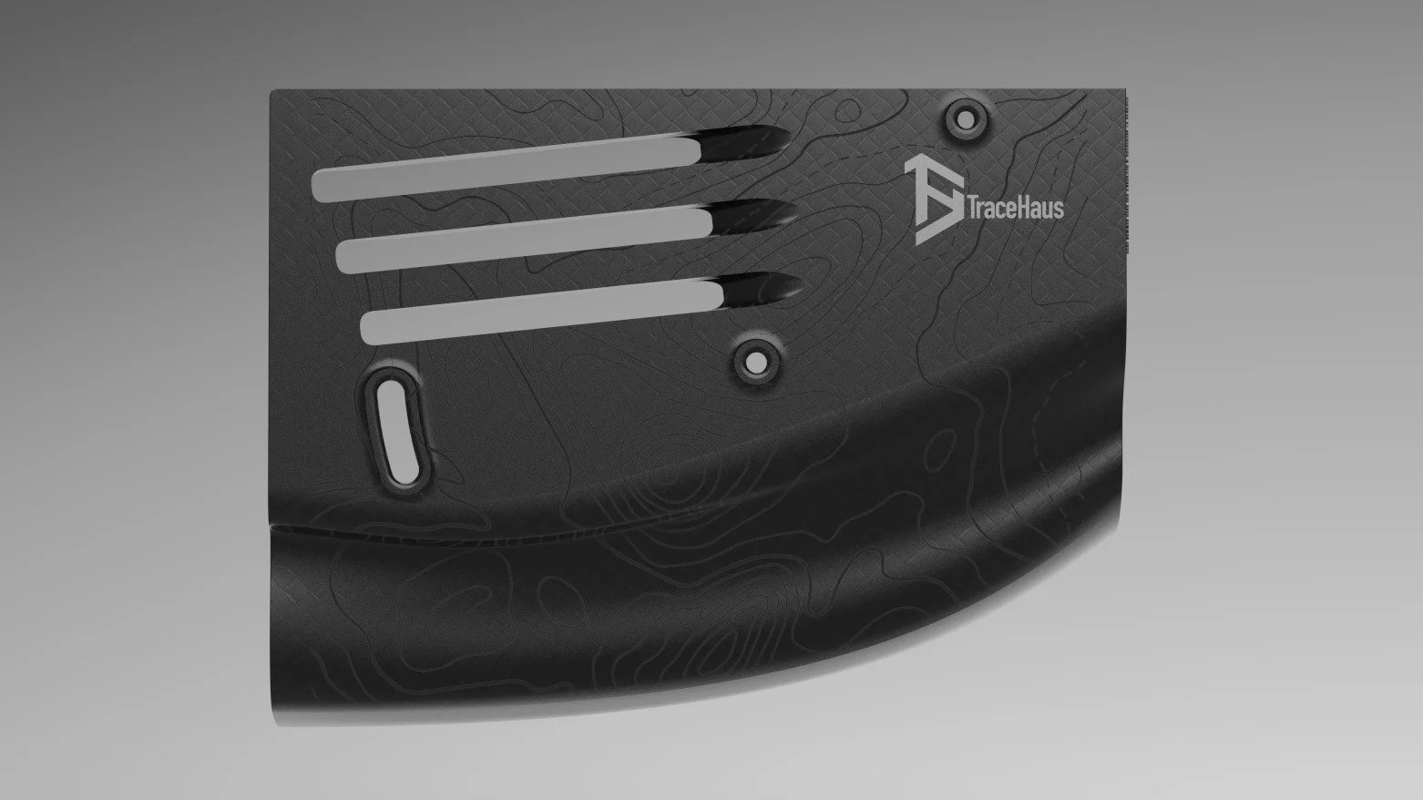
Aerodynamic Endplate Development
Parametric endplate geometry developed to manage tip vortex behavior and DRS articulation envelope.
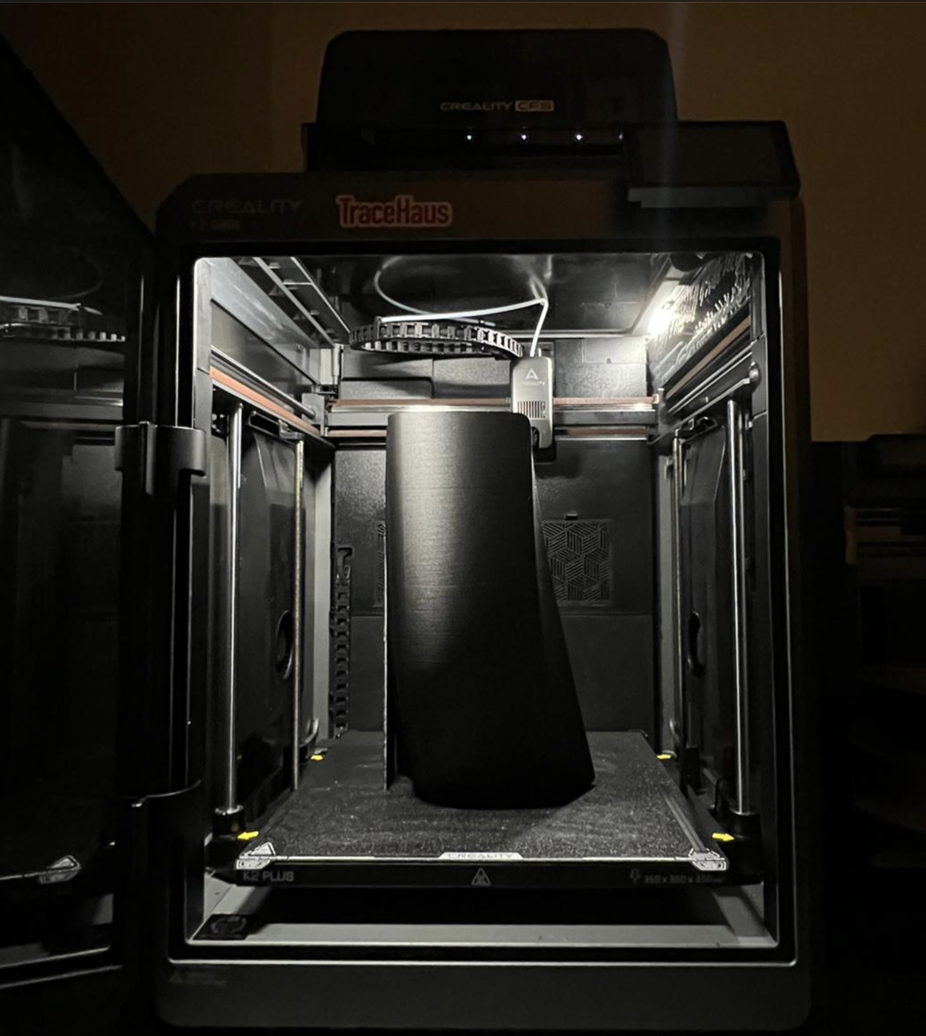
Rapid 3D-printed prototypes validated mechanical clearance, edge condition, and assembly interfaces prior to final production.
Integrated Vehicle Implementation
The DRS system was integrated directly into reinforced chassis hardpoints, with defined load paths and controlled moment transfer into the rear structure.
Mounting geometry, bracket spacing, and fastener layout were developed to ensure stiffness while maintaining serviceability and manufacturability. The system was assembled and validated under real track conditions to verify structural alignment and dynamic stability.